Here we present issues unique to the practice of architectural drawing as a subset of general graphic projection, and discuss topics in certain technical aspects of thereof. These include the commonly understood categories and terms used by architects to differentiate types of drawings, such as plan, section, elevation, axonometric, and perspectives. We also present issues in drawing to scale; standard architectural systems of notation (such as section cut lines, graphic scales and north arrows); issues in the selection and extraction of plan and section cuts; the application of the appropriate level of detail for walls, roofs, and floors in both section and elevation; and a survey of those moments that architectural drawings deviate from strict graphic projection techniques - such as in the depiction of stairs, ramps, elevators and mechanical spaces.
Architectural drawings differ from general graphic projection in important ways. The professional practice of architecture employs a number of specialized drawing types that are often based on graphic projection techniques, but depart from these significantly in terms of notation and conventions used.
Meet the Drawings (15m)
Drawing at Scale (5m)
Meet the Drawings
We begin with a general survey of drawing types we are likely to employ in academic design studios.
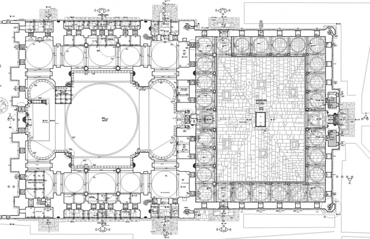
Plan
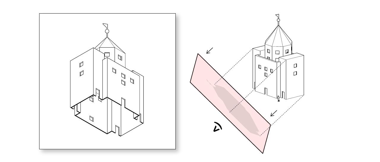
An architectural plan is a sectional drawing wherein the cut plane is positioned parallel with the ground. In most plans, the cut plane lies at some standard distance above the ground (which would be called a "ground plan") or above an occupiable floor (referred to as a "floor plan"). While following all the conventions of a typically architectural plan, a "site plan" isn't technically a sectional drawing at all, as the projection plane does not intersect any objects of interest.
Plans are the most widely used graphic device in architecture. They tend to be used to reveal:
the interrelation among the interior spaces of a design
how an occupant is able to navigate these spaces
the relationship between a building and its surrounding context.
Most aspects of an architectural plan drawing closely follow the conventions of orthographic projection, while others aspects (such as the depiction of operable doors or other moveable objects, and cuts through stairs or sloping floors) deviate from these conventions to employ notational devices.
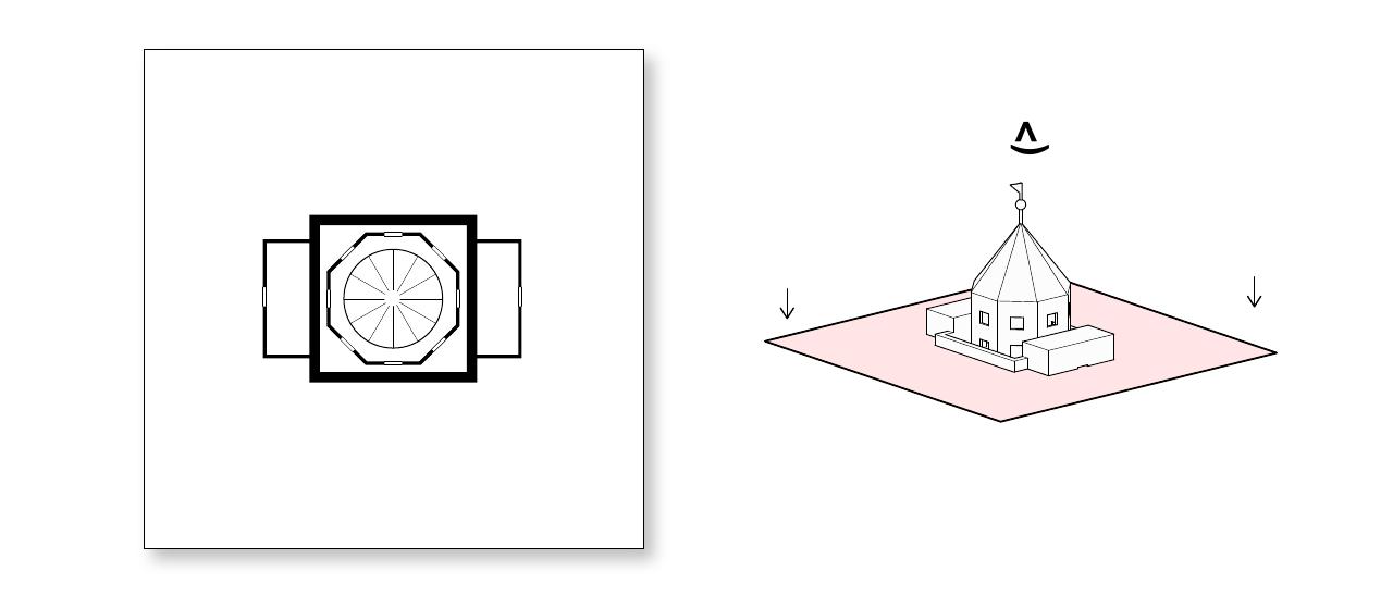
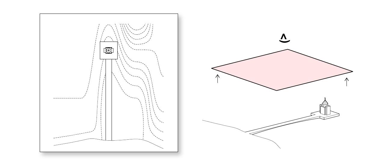
Roof Plan
A drawing for which the draw plane is positioned parallel with the ground and above the building as a whole, such that the roof of the entire building is visible. Shadows are often added to demonstrate the mass of the building in reference to the surrounding site. Typical scale: 1/16"=1' or smaller.
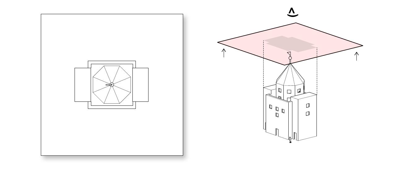
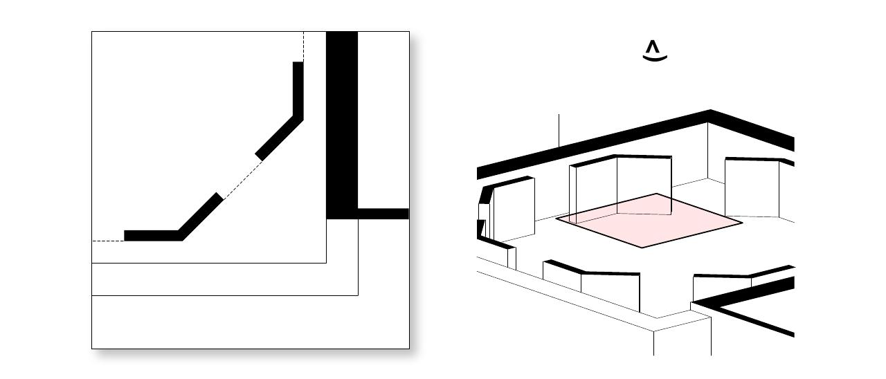
Floor Plan
This is a drawing that you'll be using often in academic studios. A floor plan is a horizontal cut through a building, typically at 3-4 ft (1.2 m) above floor level. At this height, doors and windows are represented as being cut through. However, if your drawing includes important features above the cut, you should exercise your own judgement regarding which level of cut describes your design in a better way. Typical scales range from 1/8"=1' to 3/8"=1'.
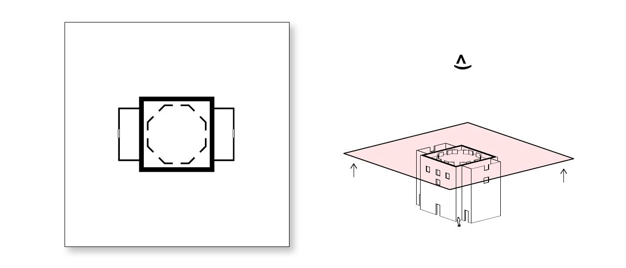
Reflected Ceiling Plan
A horizontal cut through a building, similar to a floor plan, but that depicts the elements that lie above the draw plane rather than below. The result is a drawing that "looks up" instead of down, but, unlike a standard view taken from below, the elements are projected from the same side that the view is taken. The result is a mirror-image of a standard view taken from below. The rationale in doing so is to allow elements in the reflected ceiling plan to be registered against those in a related floor plan. This is typically used to indicate ceiling grids, lighting or material patterns. You will probably not be using this type of drawing much in school.
Site Plan
A horizontal cut through all the buildings and surrounding context. It may be set around 4' from the ground to include the first floor plan, or set at a height above any built structures to show roofs, depending on how you would like to emphasize the building on the site. Typical scale: 1"=50' or much smaller.
Partial Plan
A partial plan depicts a detailed portion of a larger design. Partial plans are typically set in relationship to a complete plan that is drawn at a smaller scale, or in relationship to an elevation or section that is drawn at the same scale.
Figure-Ground Plan
Sometimes called a Nolli Plan, these drawings are horizontal cuts through an entire neighborhood or city. Buildings are represented as black poche and non-building spaces are left white. This is a popular abstraction for understanding building or city patterns.
This drawing format draws its name from Giambattista Nolli and his famous map of Rome drawn in 1748. This map utilizes the same mass to void relationship utilized in the figure ground diagram; however, Nolli added an additional layer of information which included public spaces. Thus, when one views the Nolli map, not only is the void of street elements apparent against the mass of buildings, but the voids of public spaces such as churches are visible as well.
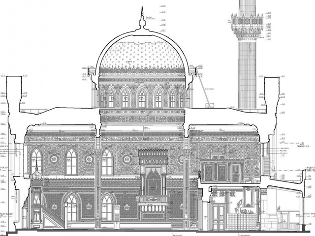
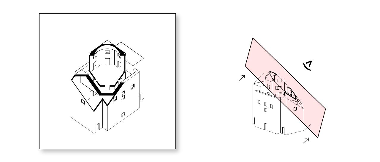
Section
An architectural section is a drawing wherein the projection plane is positioned intersecting the objects or space of interest, and is not parallel with the plane of the ground. Sections are most often perpendicular with the ground (vertical), but this is not a defining characteristic.
Sections are extraordinarily useful in architectural design, and can reveal the interior composition of wall systems, the interrelation of adjacent spaces, and the relationship between a building and its surrounding context.
Sections are often about spatial experience, but are less about organization than a plan and tend to bring up issues of construction and material.
This drawing depict spaces inside and outside a building. Context for the surrounding spaces (trees, buildings) as well as people (silhouettes) are often included to help visualize the space. Typical Scale: 1/8"=1' to 3/8"=1'.
Site Section
This is a vertical cut through the context of the surrounding site, which may include other buildings, trees, water, or other landscape features to explain the nearby adjacencies.
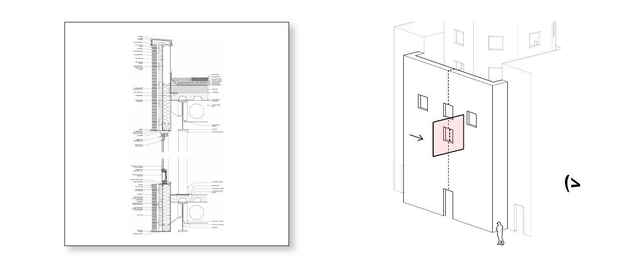
Wall Section
This section explains the construction systems and material choices by isolating just the wall, floor, and ceiling attachments on one side of the building. Wall sections detail the foundations, interior and exterior surface material thickness, and wall composition. Typical Scale: 1/2"=1' to 1"=1'
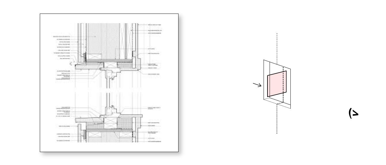
Detail Section
A partial or call-out section magnifies the scale of a small portion of a larger section in order to show more highly detailed information. These drawings typically range from 1" = 1' to full scale.
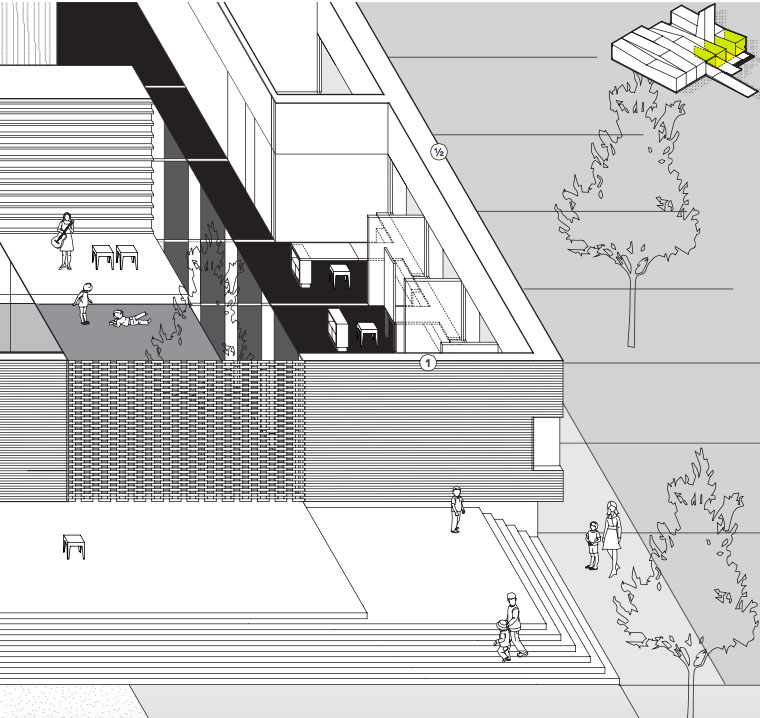
Section Perspective
A section perspective is a composite drawing which combines a section through the building, room or detail, with the perspective view that would appear beyond that cut. Not generally used in actual documentation, they are a valuable tool for presentation drawings and process and study work. They are good at illustrating the project narrative (much like a rendering) and, in place of conventional section, they may be more dynamic in conveying the relationship between spaces.
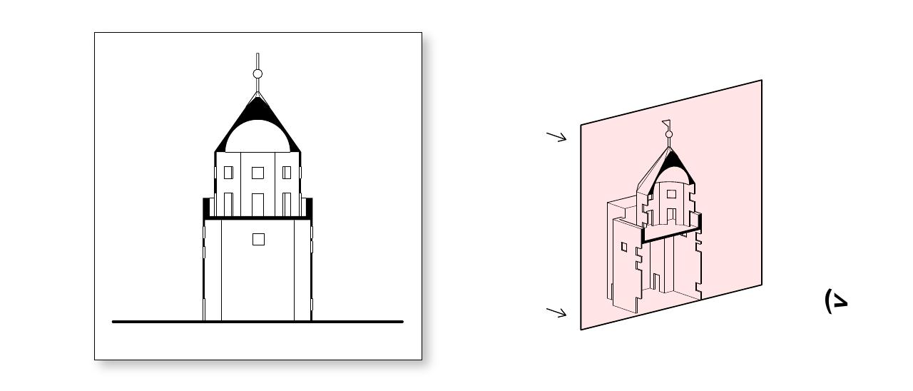
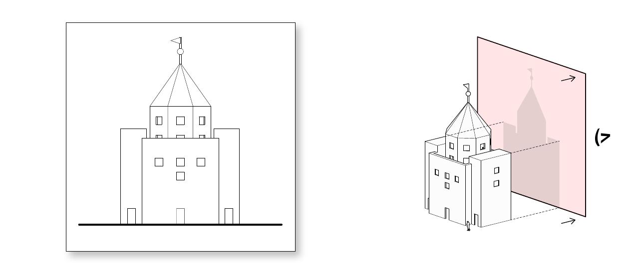
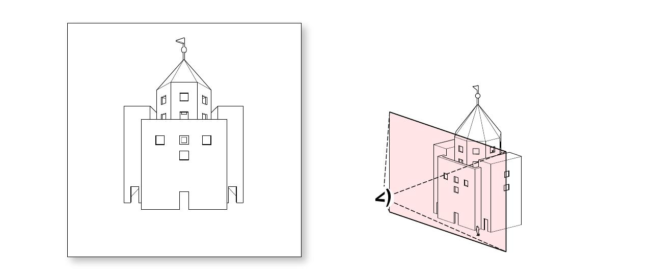
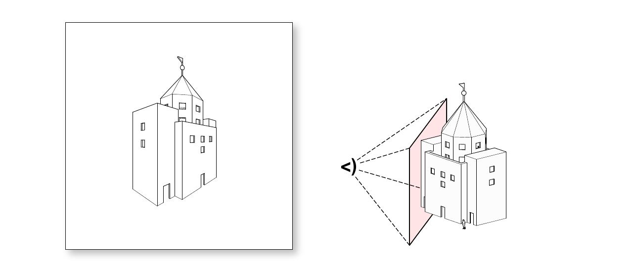
Elevation
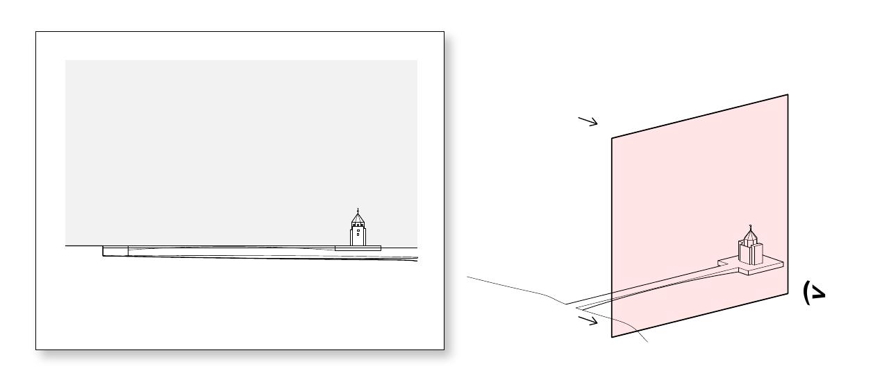
At first blush, an architectural elevation does not seem like a sectional drawing at all, as the projection plane does not intersect any objects of interest. Seen another way, we may define an elevation as an architectural section in which the projection plane is positioned near to, but not intersecting the objects or space of interest. Section or non-section: in either case, architectural elevations are useful for describing the exterior composition of a building, and the way in which it sits on a site or in relation to neighboring buildings.
An elevation is essentially a view of a building seen from one side as a flat representation of one facade and is the most common view used to show the external appearance of a building. Each elevation may be labelled in relation to the compass direction it faces; for example, the north elevation of a building is the side that most closely faces north. Since many buildings are not simply rectangular in plan, a typical elevation may show all the parts of the building that are seen from a particular direction.
All elevations are basically sections that happen to not intersect the object of interest. In some cases, where drawings have a level of complexity, in order to make an elevation facing a certain part of the building, you will have to make a section in another part. In this case, a part of your drawing will be drawn as a section and another part will be drawn as an elevation.
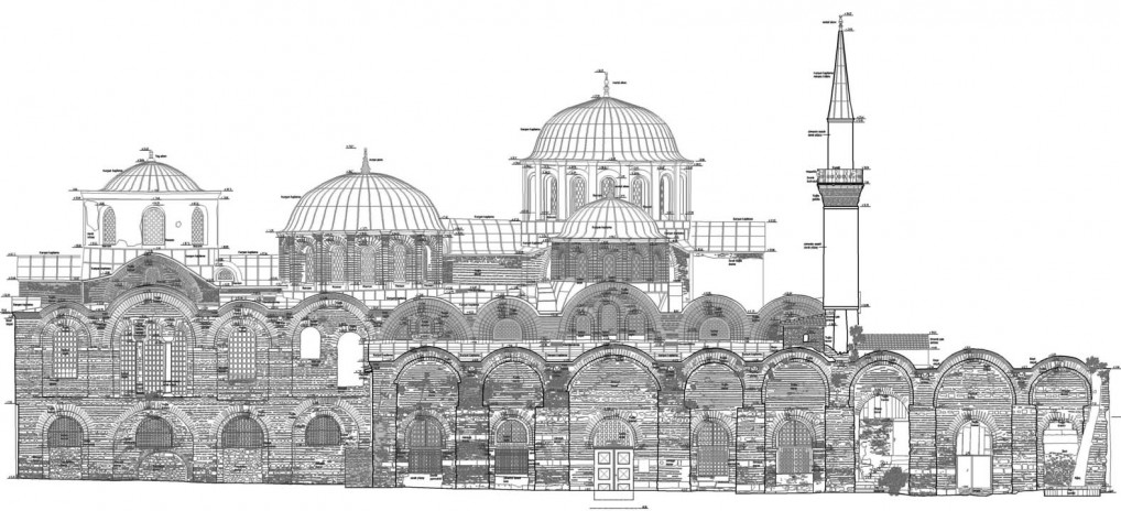
Building Elevation
This drawing is used to show the exterior facade of a building. Context for the surrounding spaces (trees, buildings) as well as people (silhouettes) are often included to help visualize the space. It is read in conjunction with plans and sections to locate openings and to coordinate other features between the various facades and the interior and exterior. Typical Scale: 1/8"=1' to 3/8"=1'.
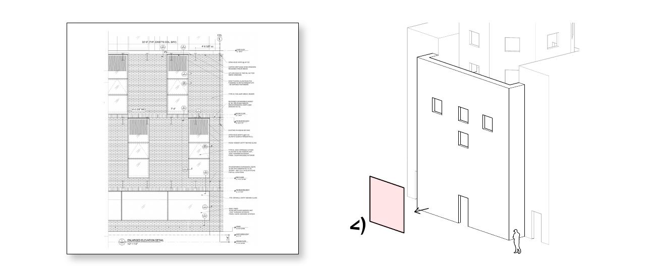
Partial / Enlarged Elevation
This drawing is used to show a portion of the elevation in more detail. In practice, this drawing is used extensively in documentation for creating shop drawings and for locating elements for construction. The view is fine enough to allow dimensioning and to make call-outs for construction details.
Partial or enlarged elevations may include context, such as the surrounding elements around a door. However, they may also show the element in isolation. This 'flattening' of elements is necessary for documentation or for creating cut files for elements that are very complex or rotated at angles not perpendicular to the plane of the view.
Interior Elevation
This drawing is used to show the surface treatments and locations for elements on the interior of the building. They can be used for spaces of all scales, from the fixture locations and material patterning of a bathroom, to the balcony height and acoustic paneling locations in a performing arts theater.
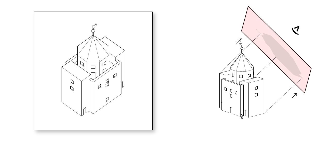
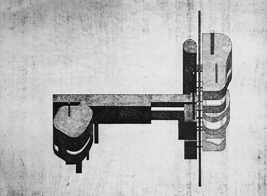
Axonometric / Oblique
An architectural axonometric is subset of orthographic projection, and includes any drawing wherein the projection plane is positioned at a non-perpendicular angle relative to the ground or the object depicted. Drawings such as this, although they depict three-dimensions, tend to take the viewer 'out' of the space in question and offer a disembodied point of view.
Classification by Construction
The wide-scale introduction of computers in the design studio has largely rendered the production of hand-drawn axonometric and oblique drawings unnecessary. Still, many architects still conceptualize and refer to perspective drawings in terms of the hand-construction techniques used to author them.
For example, although axonometrics and obliques may be distinguished by the relationship of the projection lines to the draw plane in three-dimensions, this distinction is less relevant when we consider how these drawings are produced by hand using a t-square and triangle. From this point of view, axonometrics and obliques are more alike than different, and are often referred to using axonometric as an umbrella term to describe any non-orthographic projected view that does not align with a major plane of the object depicted. Within this, distinctions are drawn based upon the nature of the resulting drawing (rather than a description of the three-dimensional projection). The primary categories most often used by architects are as follows:
Isometric
A drawing in which the three principle axes of the object depicted are set at equal angles (120 degrees) with one another, and each dimension is equally foreshortened (80% of true size). This is the most commonly employed axonometric used by architects, due to its ease of construction using a 30-60 triangle. As with all non-oblique drawings, plans and elevations cannot be used as base drawings.
Dimetric
A drawing in which one of the three the principal axes is favored to reduce foreshortening, while the other two are foreshortened equally and to a greater extent. Using this technique, one elevation is emphasized over the other and over the plan view, but due to the foreshortening, neither plans and elevations can be used as base drawings.
Trimetric
A drawing in which each of the three principal axes of the object is foreshortened independently, and to a different degree and at a different angle. These are traditionally rarely used in architectural design, but have found new (accidental) prominence in that an arbitrarily-selected three-dimensional point of view in CAD will likely result in a trimetric projection in drawing (unless the camera is very intentionally placed). Naturally, plans and elevations cannot be used as base drawings.
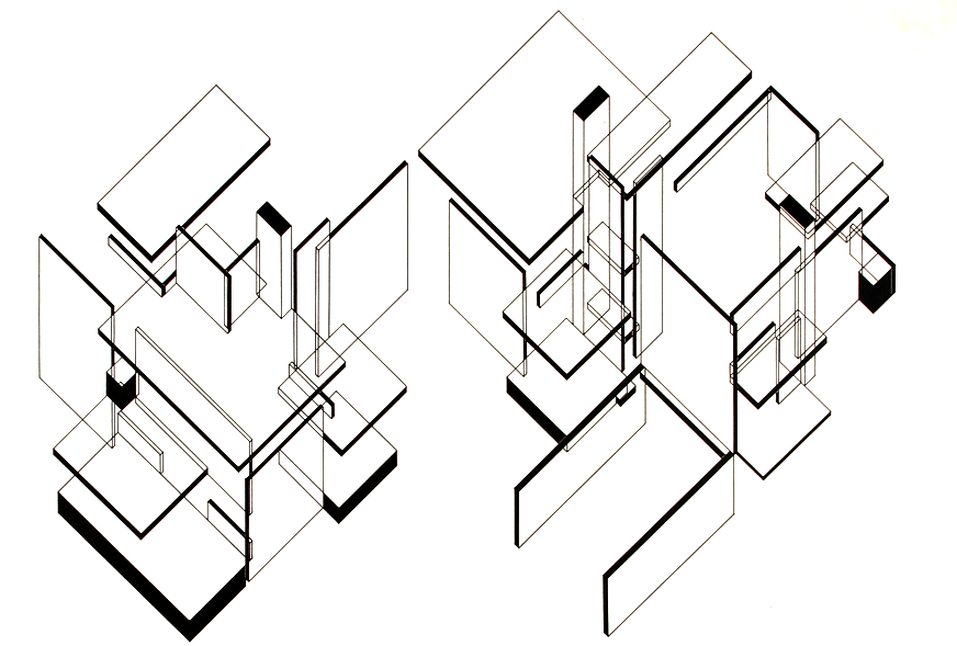
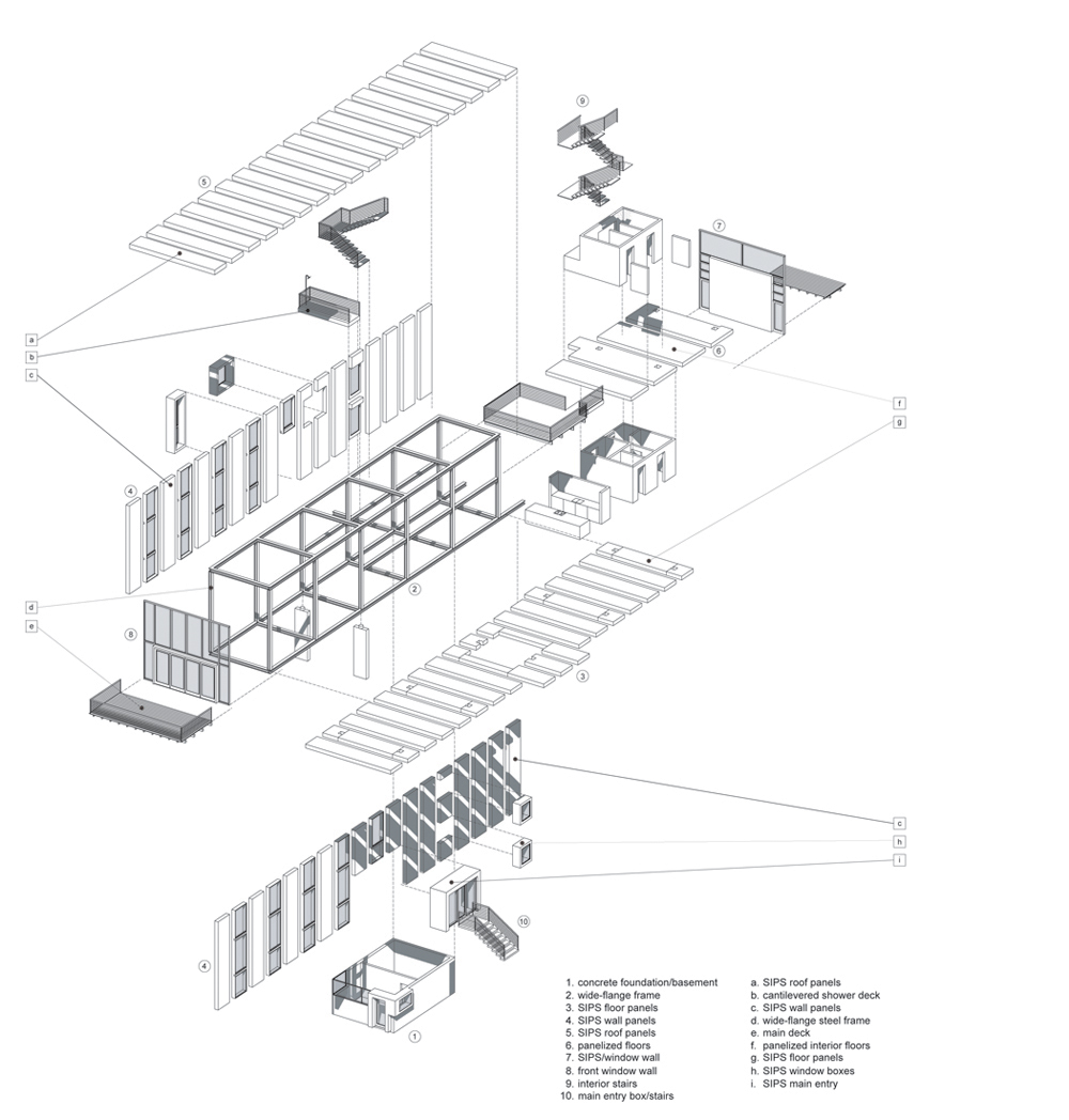
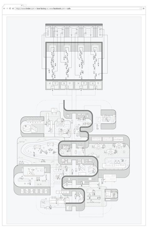
Exploded Axonometric Drawings
An exploded axonometric takes the original construction of an object and displaces selected elements to illustrate construction assembly or, in the context of architecture, spatial relationships. Exploded axonometrics can be extremely detailed, such as a construction detail, or can be more diagrammatic, such as in a program or circulation diagram.
Elevation / Section Oblique
A drawing in which two of the principal axes (the vertical axis and one other) form a plane that is depicted as parallel with the draw plane, and may be represented in true size, shape, and proportion. Here, the appropriate section or elevation drawing may be used as a base from which to draw.
Plan Oblique
A drawing in which the plane formed by the two horizontal axes are depicted as parallel with the draw plane, and may be represented in true size, shape, and proportion. Here, the two-dimensional plan drawing may be used as a base from which to draw, a feature that makes the plan oblique one of the most widely employed drawings in architectural design.