(right) Barbara Nasila, Summer 2018
While there exists a rich and varied history for the depiction of human form and gesture using hard-line drawings, we focus here on a specific approach that employs only a minimum of elaboration. We understand "hard-line" drawings to mean those vector drawings that employ an extreme economy of means, and show only black lines on a white field. Using this spartan palette, forms may represented through the careful use of just a handful of line types. We describe these below.
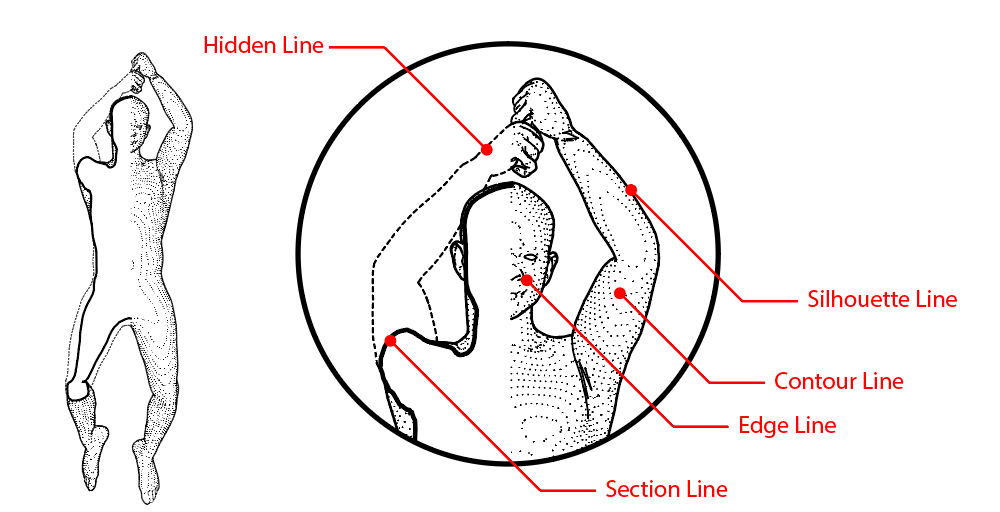
In overview, there are six line types we will use in the description of a human form in motion.
Section Lines / Cut Lines are used to describe the boundary of any forms that intersect with the cut plane of a section. These are drawn using the heaviest lines.
Silhouette Lines are used to describe the difference between two surfaces that are separated by some distance. These are drawn using medium-heavy lines.
Edge Lines are, in this context, used to describe detailed features such as the face or hands of the body. These are drawn using medium-light lines.
Contour / Surface Lines are, in this context, used to describe the surface geometry of the human form. These are drawn using lightly dotted lines.
Hidden Lines are used to describe any important geometry that has been obscured or "cut away" by a cut plane. These are drawn using lightly dashed lines.
Registration Lines are used to describe the relationship between registered and aligned views. These are drawn using very light continuous lines.
If using the template related to this talk, we may organize these line types onto the following layers.
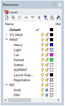
Section Lines / Cut Lines -> PRINT / Cut.
Silhouette Lines -> PRINT / Heavy.
Edge Lines -> PRINT / Light.
Contour / Surface Lines -> PRINT / Dotted.
Hidden Lines -> PRINT / Dashed.
Registration Lines -> PRINT / Registration.
Section lines describe the boundary of any forms that intersect with the cut plane of a section. We will use clipping planes to produce sectioned geometry, and rely on a feature of the Make2d command to separate the intersection of our meshes and the cutting plane.
Finished section lines should be placed on the PRINT / Cut layer of the template file provided.
Section lines show those portion of the body that intersect with the 'cut' plane of a plan or section. These are shown in heavy lines, and are "filled" with white.
Silhouette lines include any line in elevation that demarcates the difference between two surfaces that are separated from one another by some distance. Put another way, a silhouette is any line with "space behind it". This is in contrast with surface lines and edge lines which distinguish two surfaces along an edge that joins them. A silhouette includes lines that describe two conditions:
Those lines which bound the overall figure against the background
Those lines that bound some element of a form that is spatially separated from but visually overlapping with other elements of that form.
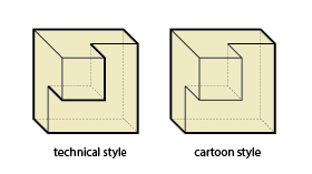
This latter category is not universally treated as a silhouette, as can be seen in the difference between "technical style" and "cartoon style" applications of line-weight in axonometric in the nearby image. Importantly, we must recognise that Rhino only produces the "cartoon" style of silhouette lines. It's up to us to correct this oversight.
Finished silhouette lines should be placed on the PRINT/ Heavy layer of the template file provided.
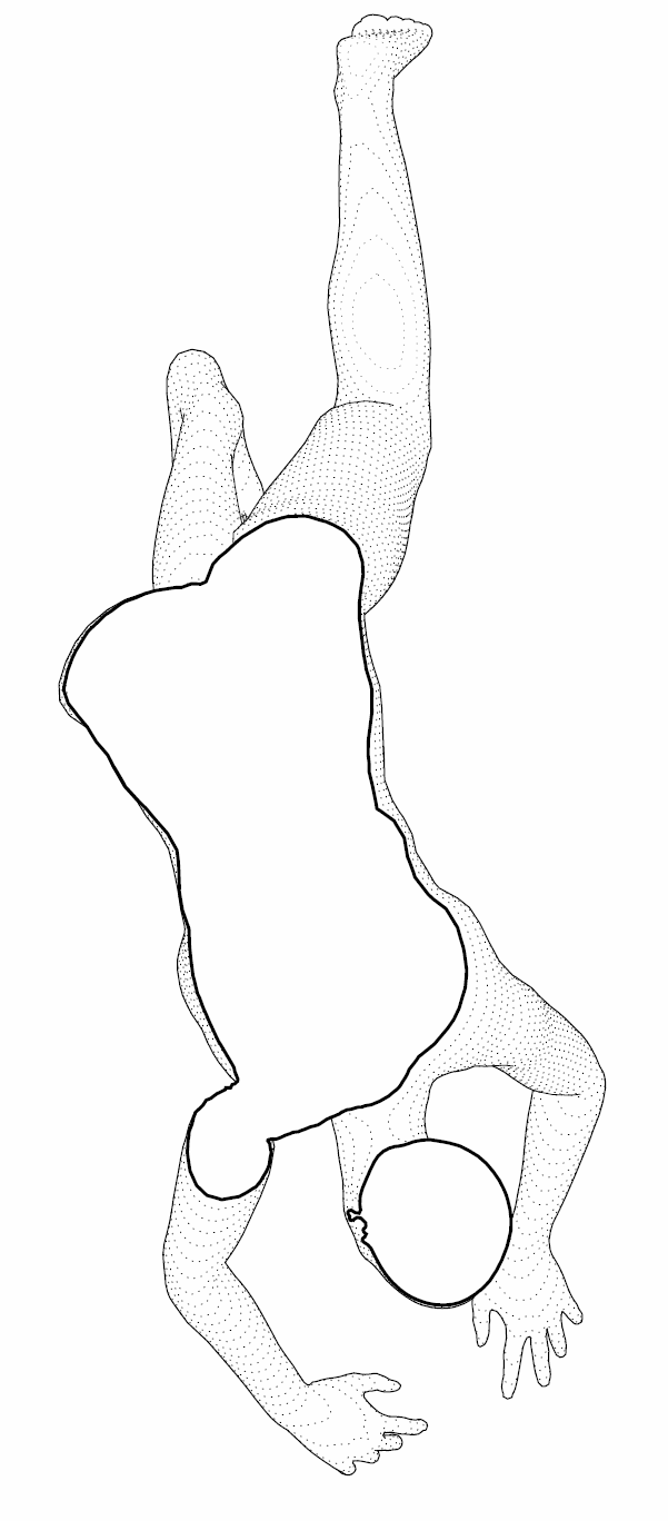
Silhouette lines show the difference between near and far surfaces with space in between, like the horizon of the earth. In the nearby drawing, note the heavy line that extends along the hip shown on the left and across the buttocks. This is a silhouette line.
By architectural convention, due to its lack of sharp corners or edges, very few conventionally-understood edge lines exist in a drawing of a human body. Still, for our purposes, we might differentiate between different "scales" of silhouette lines, such as the large fold of skin of an armpit and the small scale of the earlobe, and depict these features differently. As such, we will manually separate these different lines to be plotted at different line weights.
Finished "edge" lines should include only detailed features of the human figure, and be placed on the PRINT/ Light layer of the template file provided.
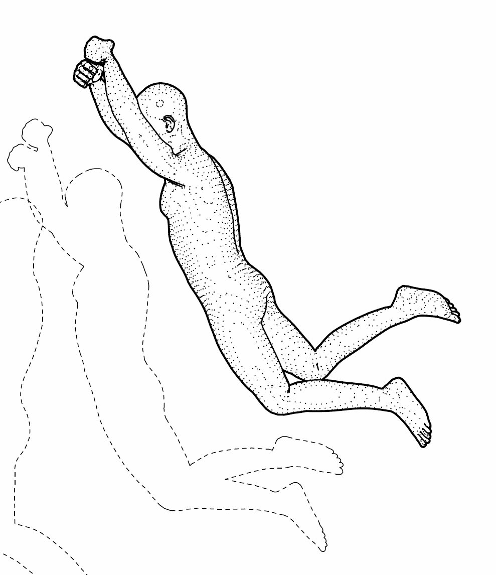
Edge lines in this context are used to show small-scale details on the human body. Note the lines used to describe the ear and the curve of the back in the nearby image. These are edge lines.
Gently curving surfaces often present a challenge to the traditions of hard-line drafting, as they do not exhibit the hard boundaries appropriate to edge lines, and can be difficult to read if left as "white" or empty space on the drawing.
There are, however, a number of established approaches to depict the texture and geometry of such surfaces. A fuller account of these techniques for drawing elevations will be left to another time, but for now, we will employ one well-known technique in the service of better depicting the human form: contour lines.
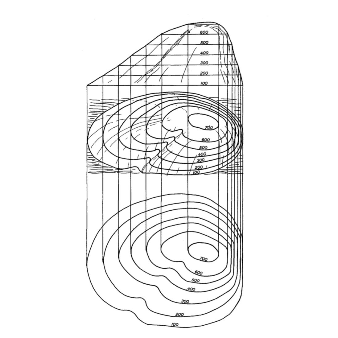
By John Rowland, 1955.
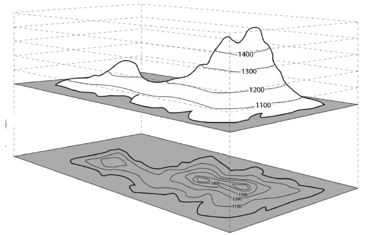
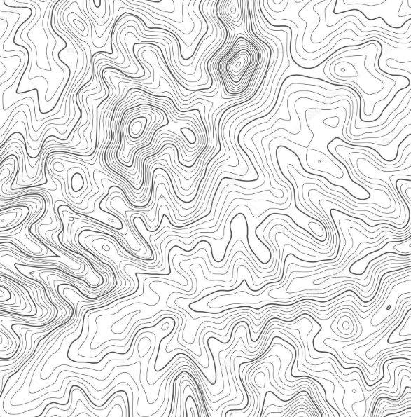
Like the lines of a topographic map, contour lines describe the geometry of a form as it intersects parallel planes at regularly spaced intervals. To produce meaningful forms, these planes must be parallel to the view plane, the way that topo lines are cut by planes parallel to the ground and seen from above.
Finished contour lines should be placed on the PRINT/ Contour layer of the template file provided.
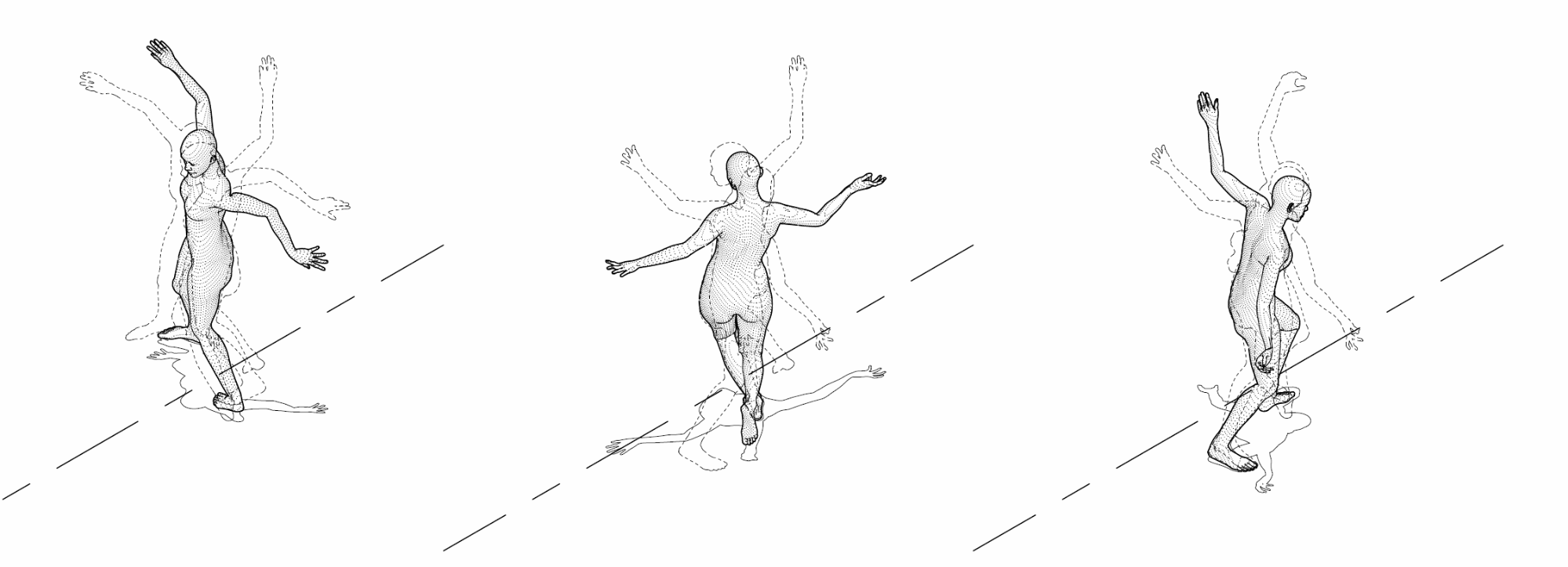
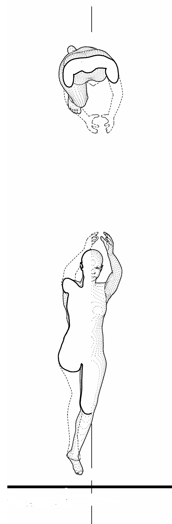
These axonometrics show contour lines that, when viewed from a distance, appear as tone.
Any important geometry that that is obscured by other geometry is considered "hidden", and may be depicted at the discretion of the author using a dashed line.
Similarly, any geometry that falls on the side of the cut plane that is removed from view (such as a prominent feature on the ceiling, like a skylight, that is above the cut plane of a plan) is considered "projected", and may also be depicted using dashed lines. For simplicity, we'll refer to both of these types of lines as "hidden" lines.
Finished hidden lines should be placed on the PRINT/ Hidden layer of the template file provided.
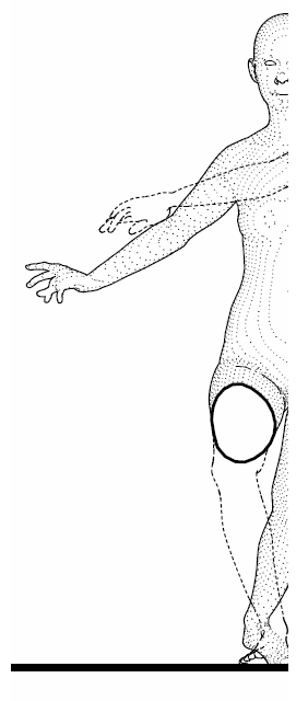
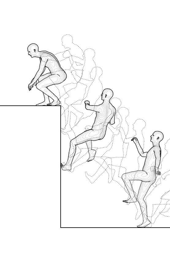
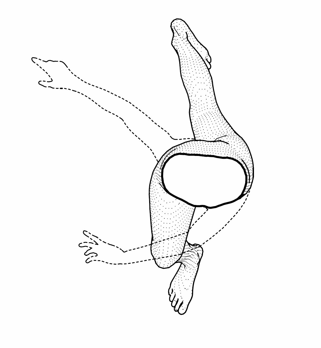
Hidden lines are used to show obscured geometry, as well as geometry that has been "cut away" by a section. The nearby image shows a section that has "cut away" the leg of the figure at the thigh. Dashed hidden lines are used to show where the silhouette of the leg would have been.