This document presents fundamental topics in the mechanics of architectural drawing in the context of graphic projection in general, and of orthographic projection in particular.
Our initial discussion will remain quite broad, and will dwell in topics that pertain to projective geometry in general, as understood by a range of disciplines from engineering, computer science, and the visual arts. We will address graphic projection in the service of architectural drawing in particular at a later time.
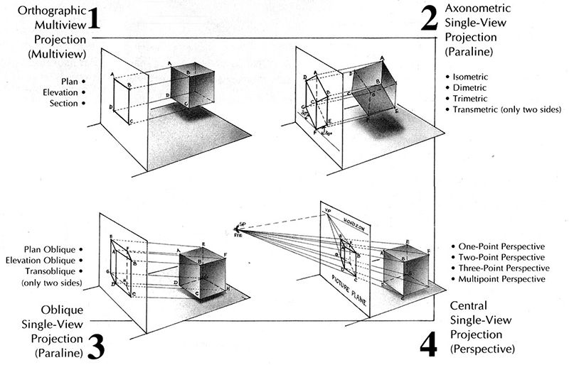
First, we present the basic elements of graphic projection. Here, some videos are shown that demonstrate the basic parts of graphic projection drawing: Image Plane / Draw Plane, Projection Rays, Station Point / View Direction. Then, we present an ontology of projection systems, distinguishing between Parallel vs Perspective Projections, and among Parallel Projections: Orthographic Views, Axons and Obliques.
Architectural drawing
is as old as
Architecture itself
By some accounts, it was the formalization of architectural drawings that established architecture as a discipline distinct from the building trades.
Graphic projection is the translation of 3d to 2d. It offers protocols by which images of three-dimensional objects are projected onto planar surfaces.
For this reason, since three-dimensional buildings are typically conceived of via two-dimensional media, architectural drawing has relied heavily on techniques of graphical projection for most of its history. Some form of graphical projection (typically parallel projection, orthographic projection, or perspectival projection) - either performed by hand or automatically generated with the aid of a computer - are employed on the vast majority of architectural drawings.
This text draws a distinction between techniques in graphic projection in general and architectural drawing in particular. While technical architectural drawing can trace its roots back to the early renaissance, and is intimately intertwined with advances in geometry and mathematics, projective geometry goes back much further: at least as far as Euclid in the 4th century AD.
Here we briefly describe the elements of graphic projection, and note how they are expressed in the four most prevalent drawing types in architectural practice.
While some of the terms presented here are used casually in practice, understanding the precise definitions can draw some helpful distinctions.
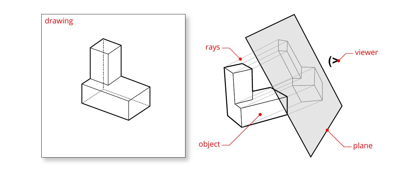
There are five primary elements at work in graphic projection:
An object to represent that presents a set of identifiable features.
A plane that receives projections of this object.
A set of rays that connect features on the object to positions on the draw plane.
A viewer of the draw plane, sometimes called a 'station point'
A set of drawing conventions by which the projected locations are re-connected to form an image.
The five elements of graphic projection are: an object, a plane, a set of rays, a viewer, and a set of drawing conventions.
Let's examine each of these, one-by-one.
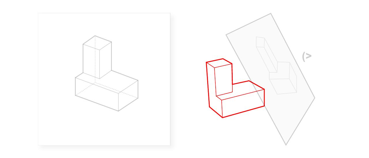
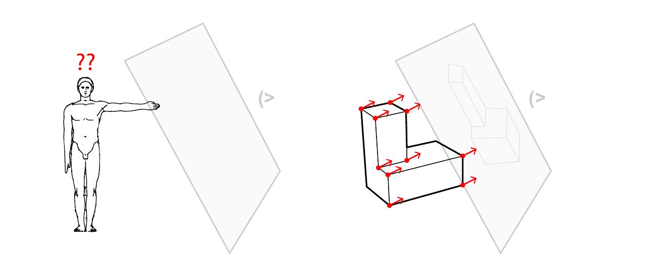
An Object
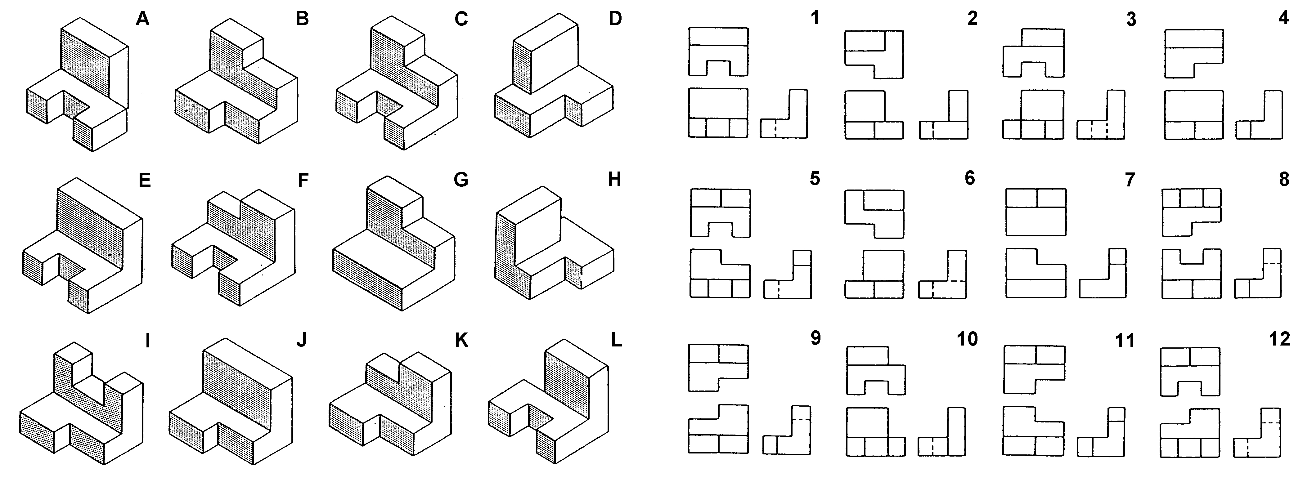
The object depicted in a graphic projection typically exhibits easily identifiable features
Some objects, such as building-like forms, offer easily identifiable features. Others, such as bodies, do not.
Some objects, such as buildings, bridges, and machines, offer easily identifiable features. Others, such as bodies, do not. As a technology that was created for a specific purpose (drawing objects made by people), graphic projection is capable of handling some objects with ease, while it struggles with others.
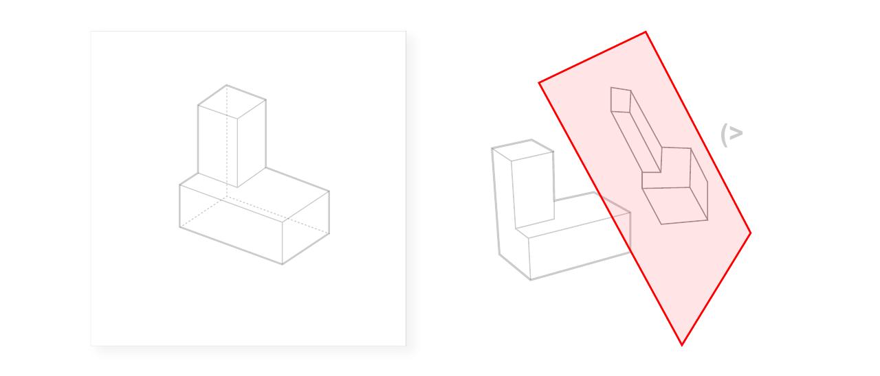
A Plane
The draw plane is the imaginary plane onto which the drawing is inscribed
Alternatively referred to as the "draw plane", "image plane" or in some cases "section plane", this is the imaginary plane onto which the drawing is inscribed. This plane may be positioned in a number of orientations outside of the object in question, and may also intersect it.
The location and orientation of the draw plane relative to the object depicted has a large effect on the nature of the drawing produced.
The position and relative orientation of the draw plane is a major factor in differentiating one type of graphic projection drawing from another.
A Set of Rays
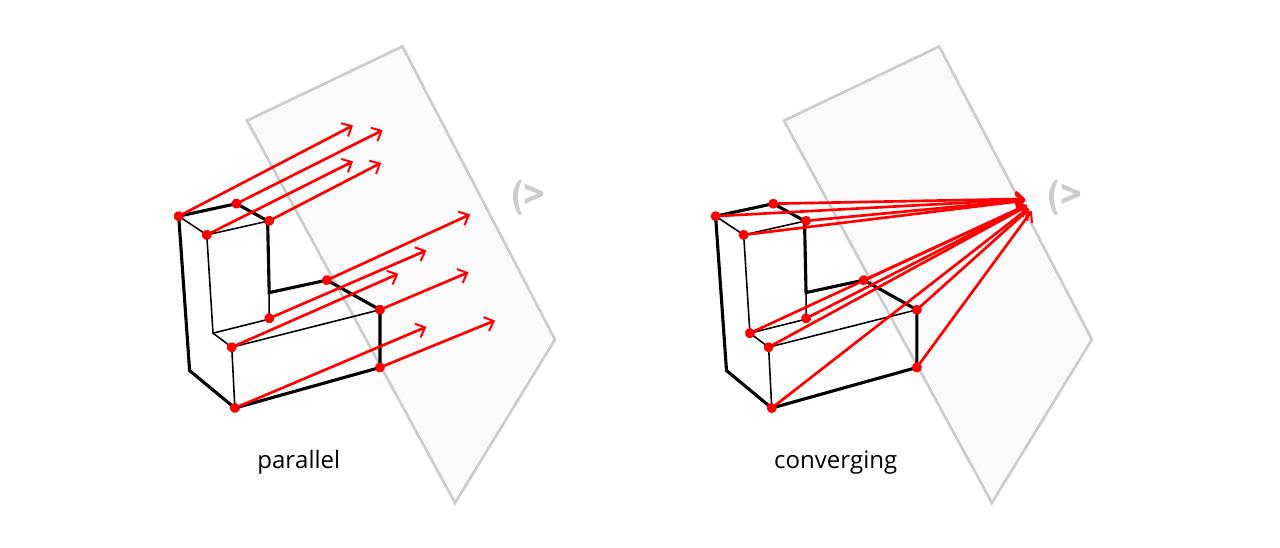
Rays that connect certain features of the object in question with positions on the draw plane. Projecting with parallel vs converging rays holds significant implications for the nature of the resulting drawing. Different kinds of graphic projections may be differentiated by the relationship of these rays to one another and to the draw plane.
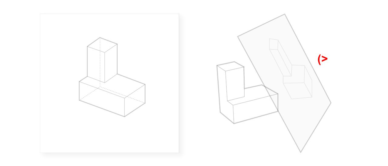
A Viewer
An indication of the position of the viewer, indicated in parallel projections simply by a side of the draw plane, and in perspective projections by a point in space.
The nature of the viewer holds significant implications for the nature of the resulting drawing.
In parallel projection drawings, the distance from object to plane and the distance from plane to viewer does not affect the outcome.
The side from which the plane is viewed, however, can affect the outcome.
In perspective projection drawings, in which lines of projection converge, the distance from object to plane and from plane to viewer, do hold a significant influence on the resulting drawing.
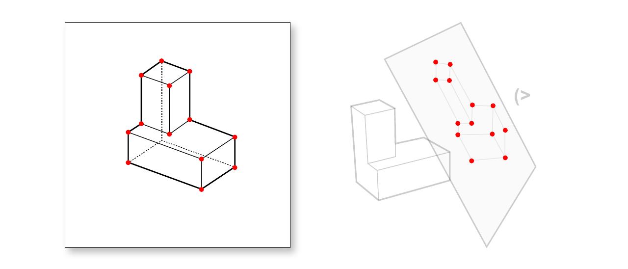
A Set of Drawing Conventions
Once a set of positions has been projected from 3d to 2d, we are left with just this: a set of locations. To move from these points to a set of lines that effectively creates an illusion of three-dimensional space and form, we rely on a timeworn set of graphic conventions that dictate the configuration and nature of these lines.
(left) Central California History Museum Perry Kulper ~2001 (right) Diagram for Courtscraper Bjarke Ingels ~2015
Conventions by which decisions are made as to how to depict (or 'render') a set of projected locations as a drawing are as varied as the discipline of architecture itself.
Traditionally, projected locations are connected using black lines of varying width and style (as described below), as the means by which architectural drawings could be produced and reproduced were quite limited in terms of tone, color, and the number of positions plotted. Even within the constraints of these limitations, a remarkable breath of graphic expression may be achieved.
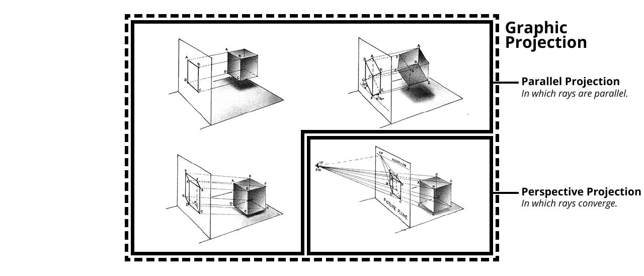
Parallel Projection (left) and Perspective Projection (right)
The simplest distinction to be made among the four basic systems of graphic projection concerns the relationship among the projection rays.
Perspective projections
Projection rays are converge at a "station point" representing the disembodied eye of a viewer. Includes 1, 2, 3, and 4 point perspectives.
Parallel projections
Projection rays are parallel to one another. Includes orthographic drawings, axonometrics, and obliques.
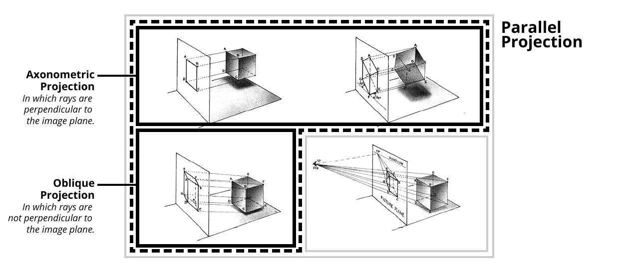
Distinctions Among Parallel Projections
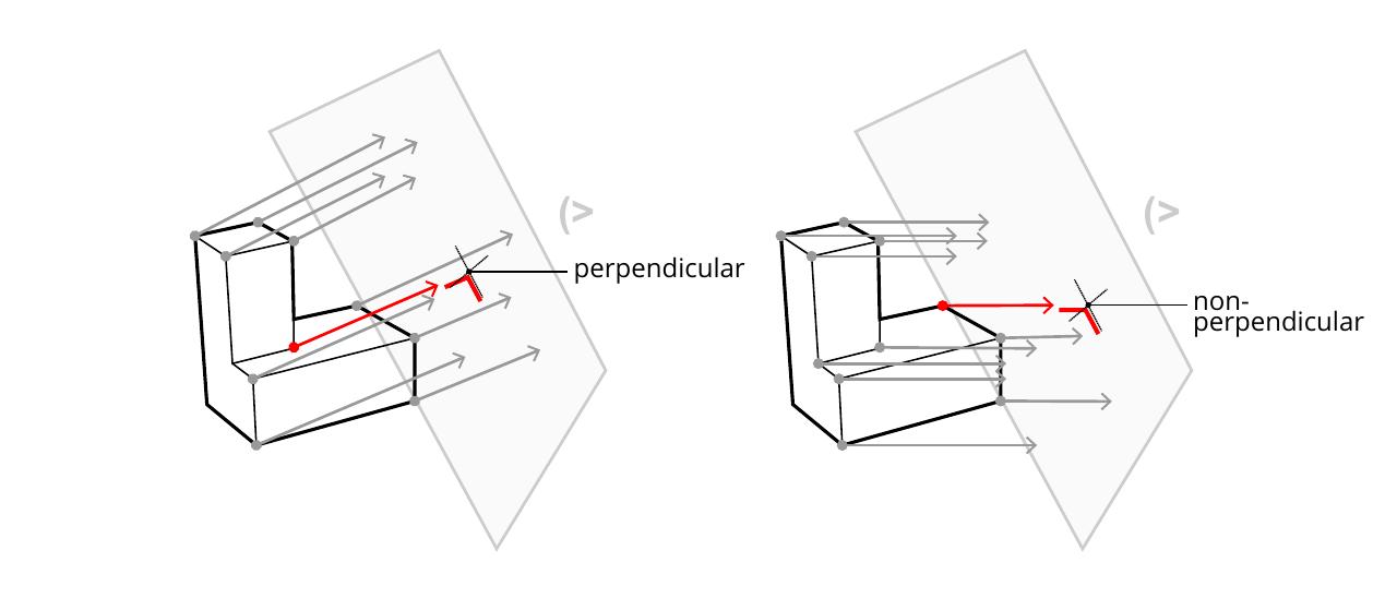
Axonometric Projection (left) and Oblique Projection (right)
Axonometric projections
Projection rays are parallel to one another, and perpendicular to the image plane - but in no specific relationship to any dominant plane of the object depicted.
Oblique projections
Projection rays are parallel to one another - but non-parallel with the image plane and in no specific relationship to any dominant plane of the object depicted.
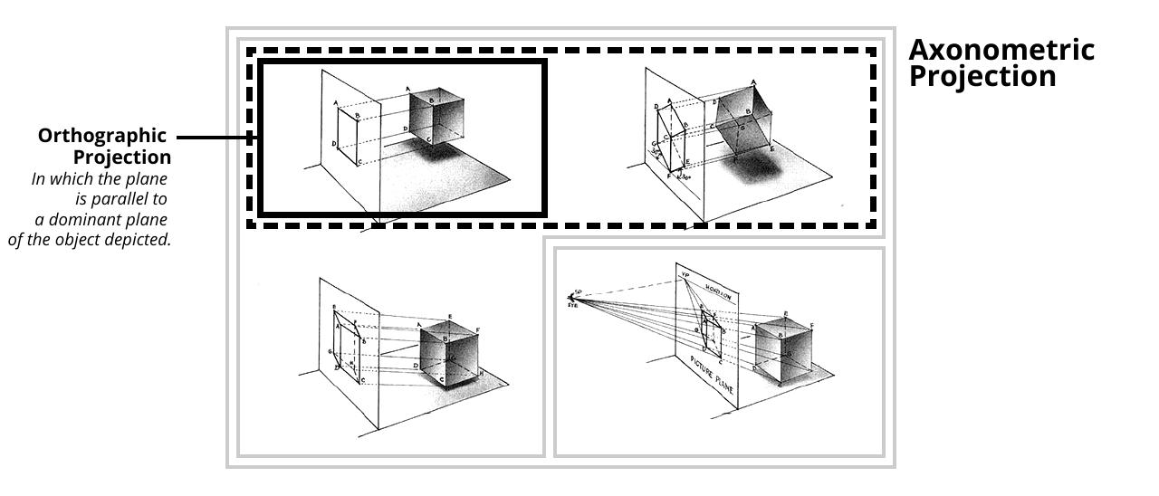
Distinction Between Axonometric and Orthographic
Axonometric Projection (left) and Orthographic Projection (right)
Axonometric projections
Projection rays are parallel to one another, and perpendicular to the image plane.
Orthographic projections
A special case of axonometric projection in which the image plane is parallel with a dominant plane of the object depicted.
Summary of Projection Systems
In Perspective Projections, rays converge at a "station point".
In Parallel Projections, rays are parallel to one another. This includes all types listed below.
In Perspective Projections, rays converge at a "station point".
In Parallel Projections, rays are parallel to one another. This includes all types listed below.
In Axonometric Projection (a special case of parallel projection), rays are parallel to one another and perpendicular to the image plane.
In Oblique Projections, rays are parallel to one another but are not perpendicular to the image plane.
In Perspective Projections, rays converge at a "station point".
In Parallel Projections, rays are parallel to one another. This includes all types listed below.
In Axonometric Projection (a special case of parallel projection), rays are parallel to one another and perpendicular to the image plane.
In Orthographic Projection (a special case of axonometric projection), the image plane is parallel to a dominant plane of the object depicted.
In Oblique Projections, rays are parallel to one another but are not perpendicular to the image plane.