Graphic projection drawings are rarely produced or displayed in isolation. Rather, they are nearly universally apprehended in relationship to other views of the same form or space. These relationships are not arbitrarily determined, but are the product of natural geometric relationships termed registrations.
A registration is a relationship borne from a shared spatial dimension.
It is by these relationships that a draftsperson constructs a graphic projection drawing, and by these same relationships that a trained viewer of this drawing is able to re-assemble a three-dimensional form. As such, the proper registration of views is an essential consideration when authoring architectural drawings.
To be properly registered, two projected views of the same object must:
Share a spatial dimension
Be arranged on the page in accordance with this shared dimension.
Let's look at each of these requirements one at a time.
Finding Shared Dimensions
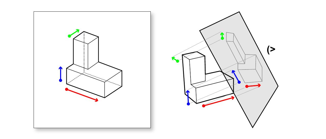
Three spatial dimensions, drawn as arrows in 3d.
We may think of a spatial dimension as something like a 3d vector (or, more properly a 'ray'), and may visualize it as an arrow with its head pointing in any direction, and with its 'tail' emanating from any point in space.
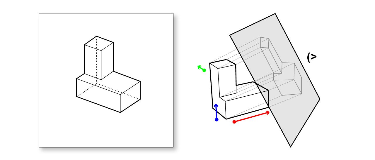
Spatial dimensions may be projected into 2d, just like other objects.
Visualized in this way, we can imagine that these arrows (and therefore spatial dimensions) may be projected just like objects. While it may not be immediately apparent in this axonometric projection, not all projections of spatial dimensions are the same.
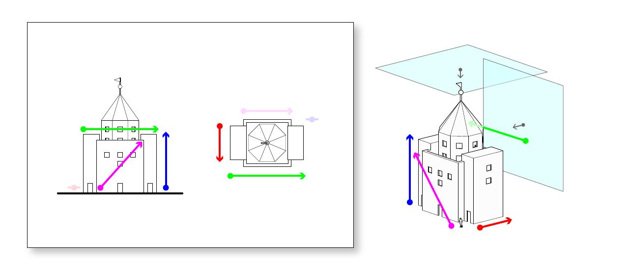
When projected into 2d, some spatial dimensions are squashed, or "foreshortened", while others appear at "true length".
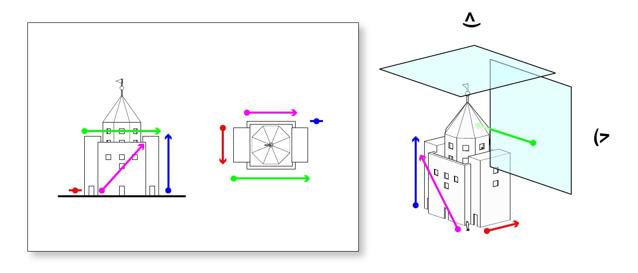
This pair of orthographic views demonstrates the different ways in which spatial dimensions can be projected. We can see here that:
Some dimensions are projected at true length, such as the blue arrow in the elevation view.
Some dimensions are "squashed" somewhat, such as the magenta arrow in the plan view.
Some dimensions are completely flattened, such as the red arrow in the elevation view.
Naturally, the fate of a spatial dimension depends on its orientation relative to a particular view. The same spatial dimension will appear differently in different views.
Only "true length" spatial dimensions count.
In order to be considered for registration, a spatial dimension must appear as true length in the related drawing. That is to say, we can eliminate any squashed ones. We might notice that the arrows that remain for each drawings are those that are perpendicular to the view direction of the drawing.
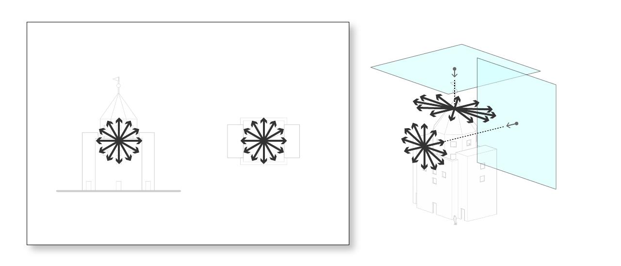
So many "true length" spatial dimensions to choose from!
Seen from this vector point of view, we could more precisely define our terms: candidate spatial dimensions must hold a vector that is perpendicular to the normal direction of the draw plane of the drawing in which they are shown. These definition captures more than just the orthogonal directions: in fact there are an infinite number of possible vectors, as shown in the nearby diagram.
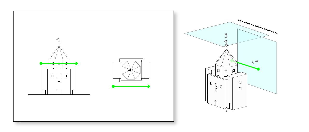
The two views shown here share a single spatial dimension.
This observation leads us to the first rule of registering graphic projection drawings: For two drawings to "share" a spatial dimension, this dimension must be perpendicular to the normal direction of the draw plane of both drawings.
In the case of the pair of views shown above, only one spatial dimension fulfills these requirements: that represented by the green arrow. We may notice that this arrow happens to align with the intersection of the two draw planes. This is no coincidence, and is the basis for the "glass box" metaphor of registering graphic projection drawings.
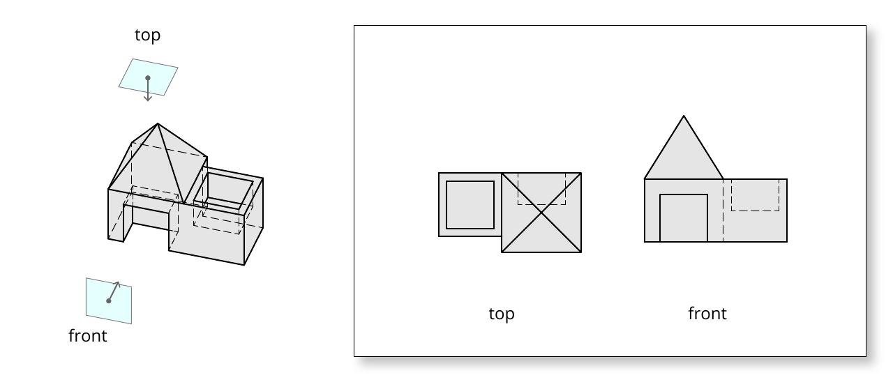
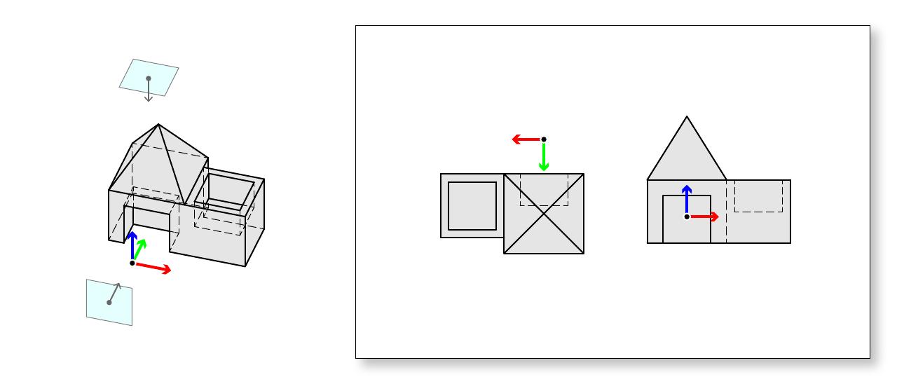
Two views of a dumb house. Note that the drawings shown on the right are *not* properly registered on the page.
As another example, consider two projected views of the form shown here.
Applying what we have learned about identifying shared spatial dimensions, can we find any that might be shared in this case?
Each of the two views of this dumb house show two out of three orthographic dimensions as "true length"
Since we're working with orthographic views, we can start by drawing the x-, y-, and z-axes of this imagined space as if they were real objects in space - shown in red, green, and blue vector-like arrows.
We can notice once more that each of our views depicts certain spatial dimensions in a "flat" (meaning undistorted or non-foreshortened) way. The top view shows a "flat" view of what we might think of as the x-y plane of the ground, and the front view shows a "flat" view of the x and z dimensions. We can be sure that the these dimensions are "flat" in that they are perpendicular to the normal direction of the draw plane.
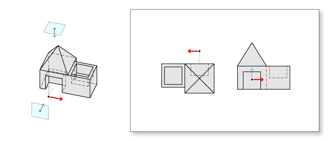
The two views of this dumb house share only one spatial dimension: the red x-axis.
Since these two views each show a "flat" view of the x-dimension (shown in red), we can say that they might be registered on the page by it. How to achieve this is the subject of the next section.
Determining Page Arrangement
Once we have determined that two projected views share a spatial dimension, we can be certain that it is possible to register them. Any such views may be regarded as being registered properly on the page if the following two conditions hold:
The shared dimension is oriented in the same direction in both drawings.
The origins of the shared dimensions are aligned on the page. That is to say, they may be connected by lines drawn perpendicular to the shared dimension.
If these conditions are met, then the drawings are properly registered.
Once registered, the perpendicular lines that connect the origins of the two dimensions may be called "registration" lines. Registration lines connect corresponding locations in each view. In this way, any object appearing at a given position along the x-axis in plan may be found at a corresponding position in the front view.
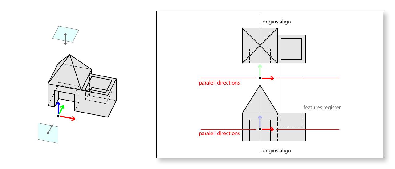
Returning to our previous example, now that we have determined that these two can "share" the x-dimension, how can we use this to register them properly on the page?
To do so, we know that:
The x-dimension should be oriented in the same direction in both drawings.
The origin of the x-dimension should be aligned on the page by lines drawn perpendicular to the x-dimension.
From this, we can see that the drawings can be arranged such that they align vertically.
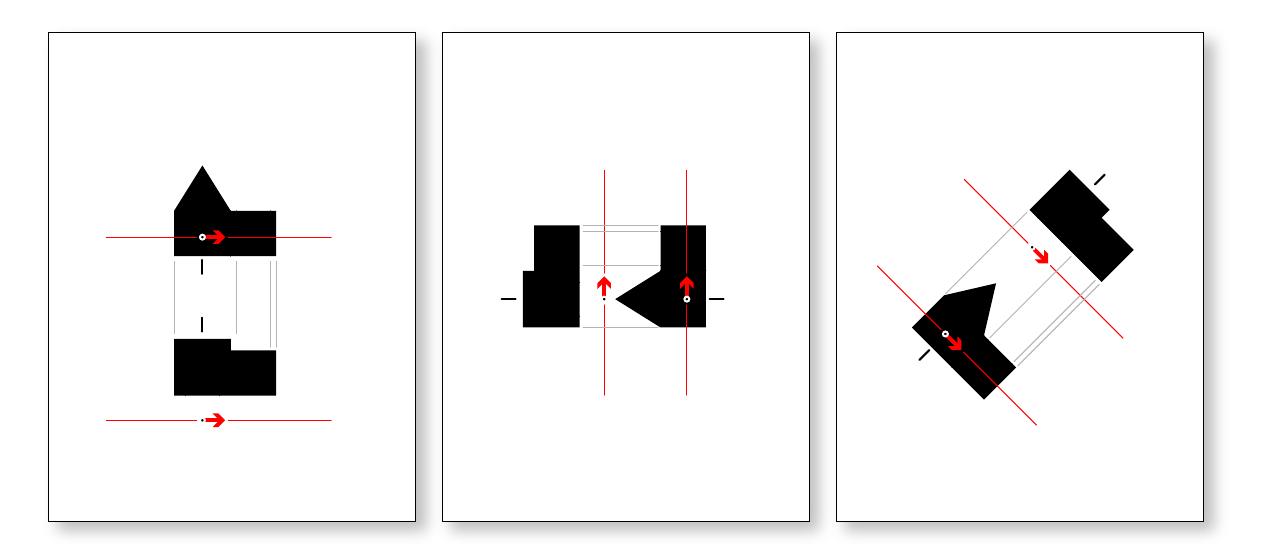
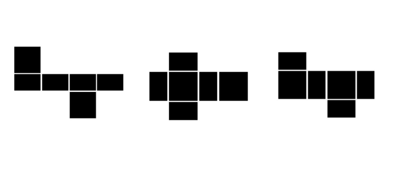
Registration among the orthographic views of an object are, by definition, a matter of arranging relationships between the six orthogonal planes. There are a fairly limited (yet generous) number of logical ways to accomplish this, and standards are well-established, as evidenced by the nearby diagrams.
Given two drawn views "share" a dimension (meeting the two conditions described above - that an axis is parallel in both views and the origin points align), it is possible to align them even if the draw planes are neither parallel nor perpendicular.
While aligning views that meet an oblique angle proceeds exactly as described above, additional care must be taken in ensuring that the "shared" dimension (which may not be the standard x, y, or z-axes, but any ray in space) is indeed shared.
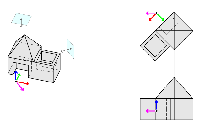
Consider the nearby diagram, which shows the registration of an oblique view (an elevation) with an orthographic view (a plan). The ray drawn in magenta is shared. Note that to keep the elevation view vertical while still properly aligning the drawings, the plan must be rotated.
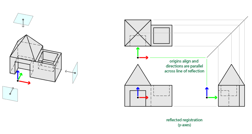
Expanding the possible layouts available to us, registration lines may be bent or "reflected" across a bisecting line. This allows us to bring more than one relationship to bear.