Since there are always multiple ways to model an idea, it is important to understand the strengths and weaknesses of different approaches in relation to the desired aim. This document presents a range of the most prevalent procedures that architects use to craft 3d-models their designs, and the tools that support them. We aim to better understand the available options for making 3d models, and how these specific options differently support design ideation.
After a broad discussion of the uses of CAD modeling, we present three general approaches to modeling in 3d - wireframe, solid body, and extrusion modeling - each of which carries its own set of implied geometric operations, software tools, and workflows.
Of primary concern when sitting down to create a 3d model is the anticipated use of the result.
While the completeness of 3d representations can lead us to regard these models as ends in themselves, we would be wise to remember that they are means to project a possible future. Like all representations, they are inherently incomplete reflections of what we imagine our designs to be. As such, their utility is strongly related to their ability to facilitate useful projections into the future.
This is the metric by which we decide what information we embed in them and what processes we use to author them.
Three-dimensional representations are no more universal than any other. Although they can feel like objective models of the "real" world of our designs, they are not perfect reflections of reality, and not a complete representation of the world. Rather, they are a cultural artifact, and reflect the only information that we put into them. They are useful only so far as they are able to effectively generate the information we require of them.
The model we use to produce drawings will be different from the model we use to produce renderings, or the model we use for fabrication. This is because each of these uses offers its own unique requirements and constraints.
We describe here three broadly-defined reasons for producing a three-dimensional model.
Three very good reasons to make a 3d model, from left to right: Modeling for Drawing, Modeling for Rendering, Modeling for Fabrication
Modeling for Drawings
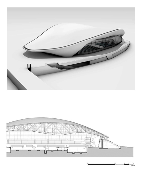
3d model and section drawing of London Aquatics Center, ZHA
Very often, 3d models are prepared as an antecedent to 2d drawings. This is especially true for academic studio design, in which much of the product of our work is presented in printed two-dimensional formats. In these models, interior and exterior are given equal importance, as is (depending upon the type of drawing produced) the general massing and assembly of the design.
In this endeavor, it is important to not be carried away by the implied totality and completeness of the three-dimensional model. Foremost, the seeming completeness of the digital model presents a hindrance to ambiguity, and offers a hindrance to the reflective loop so important to design. In addition, the scale of the resulting drawing will directly and greatly influence the amount of detail that is included in the 3d model. One should take into consideration how three-dimensional information will be reduced to two-dimensions.
Consider what elements of a building will be 'seen' from the drawings in question. Test-print as the drawings develop in order to ensure their legibility, and that details are not being unnecessarily resolved. Often, 3d models are over-detailed for the drawings they are used to produce, and must be simplified.
Rhino's Make2D command offers an easy way of translating 3d models into 2d drawings, but are the assumptions built into this procedure a good fit for the task at hand?
Consider the following guidelines when preparing a model for a 2d drawing:
Let the Drawings Lead
When modeling for drawings, it's easy to allow the direction of the model-to-drawing workflow remain a one-way-street. Rather than let the 3d model dominate, which by definition carries more geometric information and requires more careful resolution of conflicts, allow design changes to freely occur in 2d before resolving them in 3d.
Model for the Drawing you Need
The drawing extraction processes carries over into two-dimensions the structure of things in three dimensions. If you model your wall as 1000 overlapping blocks, you'll get 1000 overlapping rectangles in your section. Avoid this by anticipating the continuity of section cuts, elevational lines, and intersections that you'll need to 2d drawing as you develop your 3d model.
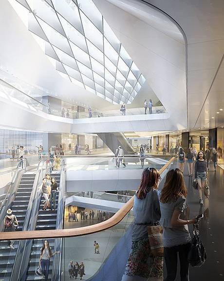
A major use of three-dimensional models in both academic design studio and in practice is rendering. Here, the visual presence of the design is paramount, and the detail and attention given to a model is highly dependent upon the point of view depicted. Non-geometric qualities such as the application of materials and the presence and performance of light are critical, while certain geometric features (such as the thickness of glass at certain scales and non-visible assembly details) are stripped away.
Again, while our tendency may be to include as much detail as possible in a 3d model in order for it to appear "correct" in renderings, much of this detail is unnecessary or even harmful. For example, excess geometry in the model (that must go through ray-tracing to determine how light reflects off of it and into the camera) will add to the render time and hinder the model author from iterating. Many of the appealing spatial qualities of renderings are prepared in a "post-processing" step in a raster image editor (such as Photoshop), and would have required complex materials that would take many hours to render in 3d.
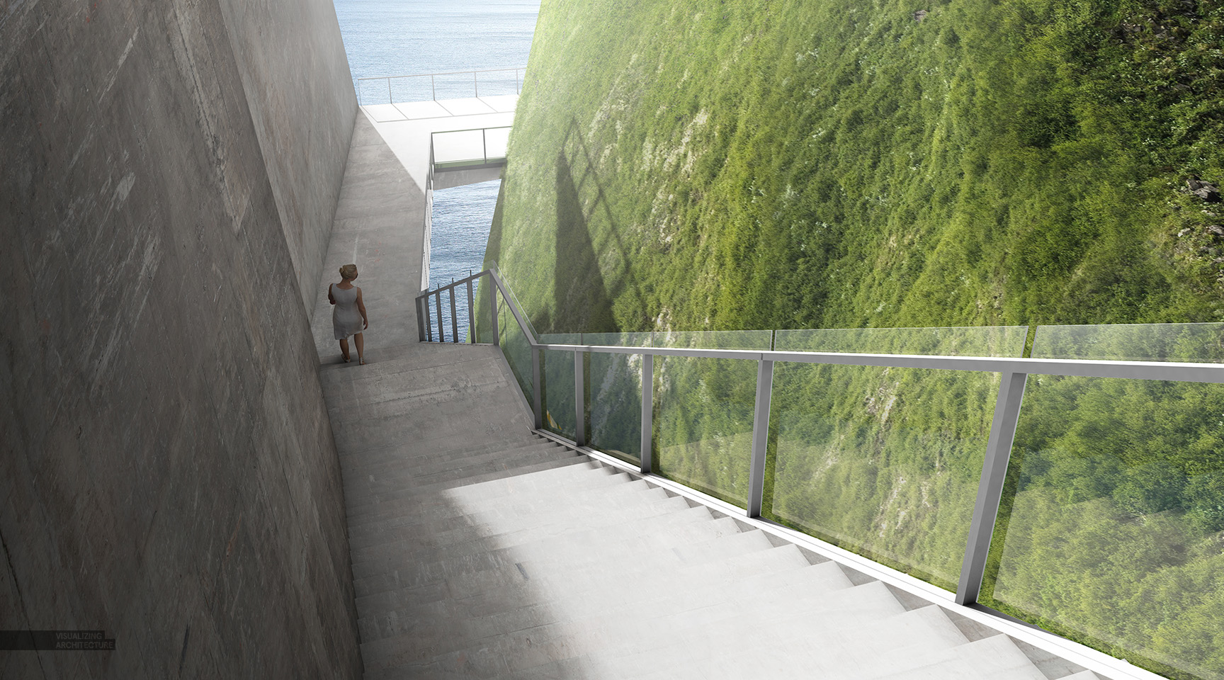
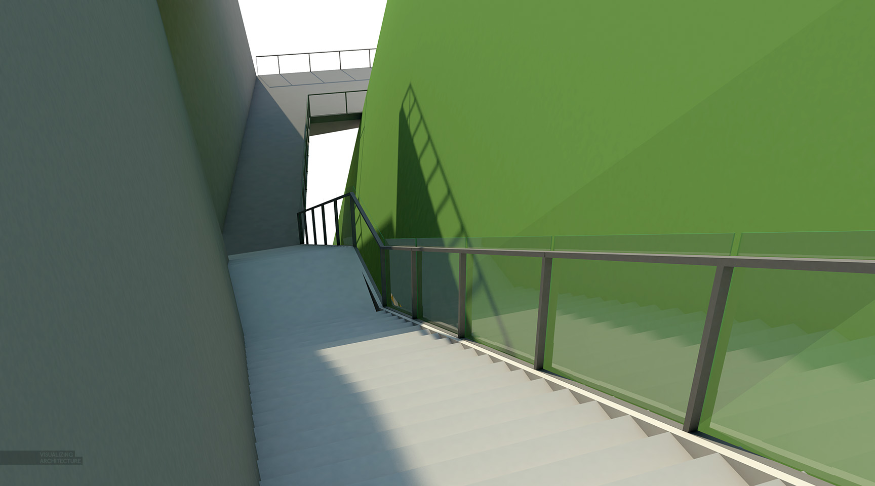
For a thorough treatment of this and other topics in rendering, see Alex Hogrefe's excellent website on visualizing architecture.
Geometric modeling has less to do with the quality of architectural rendering than we might think. Consider the simplicity of the 3d model as it appears in the 'raw' rendering (left) in comparison to the final image after post-processing in Photoshop (right). Alex Hogrefe, 2015
Consider the following guidelines when preparing a model for a rendering:
Detail Selectively
It is only necessary to model the geometry that will be seen by a particular view. Tiny details, such as door hinges, fasteners, detailed window mullions, will not be seen in most architectural scale renderings, and will only take precious extra time to render. Also, detail can be added for elements that appear close to the camera, and left out for those far away from the camera.
Split it up
Given the principles outlined above, it is often desirable to produce separate models for each rendered view. Using this approach, we can include only those details that are needed for any one view.
Keep it simple
It's best to keep the complexity of materials in your renderings to a minimum and consider how you can use Photoshop to achieve similar results in less time.
Unlike modeling for the production of 2d drawings or renderings, modeling for fabrication (which can include laser-cutting, 3d Printing, CNC-milling, or full-scale fabrication) offers far more demands in terms of precision and coordination. Because this sort of modeling is heavily dependent upon the material, method of construction, restrictions of the mode of fabrication, and the scale of production, it is difficult to offer specific guidelines outside of this context.
To illustrate the issues involved, consider the differing dimensional issues in laser-cutting, 3d printing, and CNC-milling: The typical minimum size that a laser cutter can cleanly cut out of most materials is 1/8" - any lower than that and we come increasingly close to having a thin, mostly incinerated and unusable piece for the model. 3d printers however have restrictions set by the printing material, whether it's starch, plastic, or another medium. Finally, CNC mills are mostly restricted by the drill bits available and the stock used to be milled.
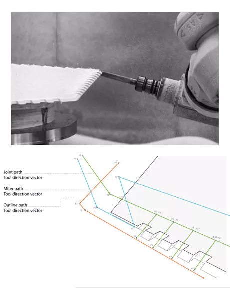
To illustrate how intimately modeling for fabrication is tied to the details of realization, consider the issues involved in a seemingly simple task of drawing bolt-holes.
Bolts are measured in terms of both inside diameter and outside diameter of the threads, and are manufactured to specific tolerances. To ensure that a hole we draw in our CAD model is the right size for the bolt specified, we need to understand the differences between these dimensions. Furthermore, we need to understand how the geometry we produce is interpreted by the fabrication process. At times, we will draw the results we wish to end up with, and at other times we will draw the information used to drive the machine. These are different. In the case of our bolt holes, the centerline of the path of the CNC router head should not follow the diameter of our desired bolt hole, but rather should be offset by a dimension related to the diameter of the router bit. Without this information, and without a discussion with the fabricator, we will not be able to model effectively for fabrication.
The best practice in each of these situations is to consider the scale of the design that we're producing, and to coordinate well and coordinate often with the machine operator and/or fabricator to better understand the capabilities of the machine and the restrictions of the process.
General Approaches to Modeling in 3d
In any creative media, it is not simply the nature of the tool but also the hand of the author that determines the quality of the completed work. As such, when discussing three-dimensional modeling, it can be helpful to look beyond the capabilities of software tools, and to the cultures of use that these tools enjoy in practice.
Here we present three general approaches to producing 3d models, discussing dominant approaches, typical applications, and common tools inherent to each.
Wireframe Modeling
Solid Body Modeling
Extrusion Modeling
These three approaches are not meant to represent an exhaustive list, but rather to serve as a guide to the novice user of 3d software and as an illustration of the interrelationship of tools and methods.
It's important to note that the different approaches are not mutually exclusive to software. For example, Rhino can serve as a "Wireframe to Surface" modeling tool as well as an "Extrusion" modeling tool. Since these approaches are as much social as they are technical, they must take into account the commonly-found methods of working as much as the capability of the software. That is not to say that the nature of software is unimportant: software is developed with specific use-cases in mind, and can be more or less supportive of particular approaches.
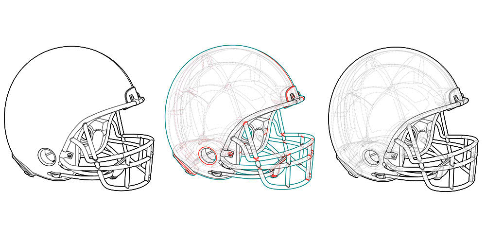
The Wireframe-to-Surface Approach
The Wireframe to Surface modeling method starts with a set of construction geometry - such as wires, frames, and jigs - and slowly builds this up via operations that produce surfaces. This approach values the precise and iterative definition of surface-based forms and the calibration of surface properties, and de-emphasizes the gestural or playful aspects of modeling. Tools are often offered for the quantitative inspection and analysis of resulting forms, and highly directed and repeatable workflows are often used to carefully iterate toward a desired aim.
It may be useful to think of Wireframe to Surface modeling in terms of aerospace or nautical design, as many of the tools, methods, and software have been borrowed from these industries. For example, CATIA has been a standard tool in the design of commercial aircraft for decades, and was adopted and adapted by Frank Gehry's office in the early 2000's as a related product called Digital Project.
The 'wireframe-to-surface' approach to 3d modeling emphasizes the use of construction geometry to incrementally build up surface-based forms.
Implied Operations
Surface Construction (Sweep, Loft, Revolve, etc)
Incremental Iteration
Jigs + Results
Software
Rhino: A NURBS-based 3-D modeling software. Developed first with ship-building and jewelry design in mind Rhino works most easily with curves and surfaces.
3ds Max: While this software also appears in the Solid Body category, a close look at the workflows supported demonstrates how the wireframe-to-surface method can be used in this software as well.
Related Workflows
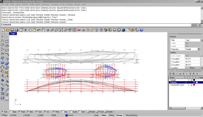
Surfacing a Site Model
Using a digital model to prepare cut files for a physical site model using the surface modeling method. Involves the use of the Rebuild and ExtractWireframe commands before using the SrfPt command to build new triangulated surfaces.
Best Practices in 3d Modeling - Jigs and Construction Geometry
This workflow details methods for the use of construction geometry and "jigs" in 3d modeling as a way of ensuring consistently, accuracy, and agility in adapting to changing design parameters. The utility of construction geometry will be demonstrated through the case-study of modeling a 3d kayak based on 2d contour information.
The Solid Body Approach
Solid Body modeling is much like it sounds: forms in space are instantiated as primitives, and manipulated as if they were solid forms, rectilinear or amorphous. This approach to modeling relies more on the intuition of the author, offering fluid and gestural interfaces for the quick iteration and visual evaluation of forms. Tools that support this approach often aim to follow after analog methods, and to convey a sense of sketching or sculpting. Tools that employ physical analogs are often offered. Since workflow repeatability and incremental iteration toward a quantitative end are de-emphasized, this approach may be criticized as feeling "inaccurate".
It may be useful to think of the solid body approach as being related to animation and character design, as many of the tools, workflows, and software (such as Maya and Modo have been borrowed from this industry in which expressive form and rendering styles are valued more highly than accurate modeling for performance.
The Embryological House, 1997-2002, by Greg Lynn was an early exercise in the powers and pitfalls of solid body modeling. The project was digitally modeled in MicroStation and Maya.
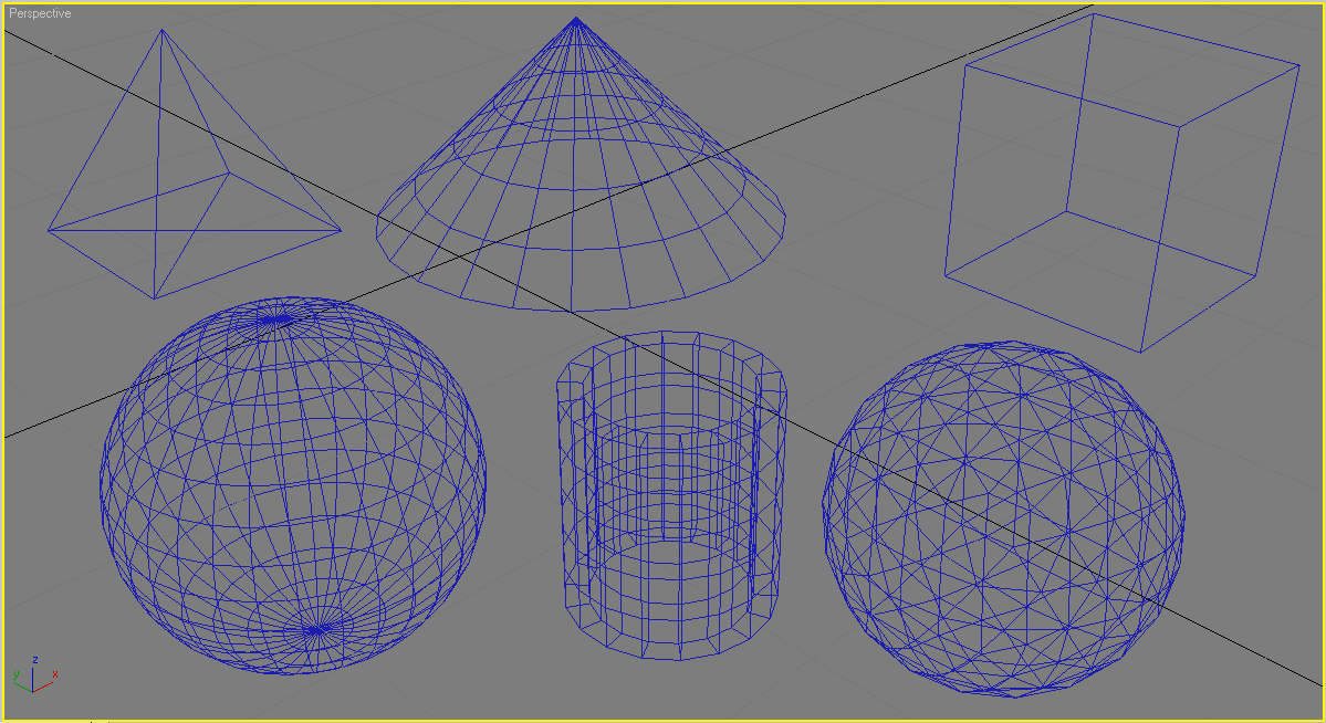
The 'solid body' approach to 3d modeling emphasizes the creation and manipulation of primitive geometry.
Implied Operations
Boolean
Aggregation
Translation
Transformation
Control Points
Software
Maya is a 3d computer graphics software. It is fundamentally an animation modeling software used for video games, 3d film, and animated effects. It was developed to make complex digital scenes with objects, backdrops, and lighting. Maya is also used in architecture but in conjunction with other programs with more facility in accuracy.
Modo is a 3D software that combines modeling, painting, animation and rendering in a fused workflow for designers and artists working in the areas of industrial design, architectural visualization, package design, game development, film and broadcast, education and scientific studies.
3ds Max, like Maya, is essentially a 3d animation software used primarily for videogame environments.
Related Workflows
Creating a Program Circulation Diagram
This workflow demonstrates how a simple massing can be programmed with boxes to divide and discern the location of the various circulation and programmatic elements
Three Approaches to Massing Models
This workflow showcases three different modeling strategies for creating abstract models exhibiting double negative space. These three different methods cater to different surfaces tools in Rhino as well as different formal and spatial strategies. One method focuses on creating extruded volumes from existing linework, one from solid geometry, and the last method focuses on creating lofted surfaces from 3d construction geometry and/or jigs.
The Extrusion Modeling Approach
2d->3d techniques are the most traditional in that this approach to modeling directly utilizes measured plans along with elevations and sections to create 3d form. The 2d -> 3d method is accurate and quite good at modeling relatively traditional walls and floor plates. The 2d -> 3d method can model simple extruded curves, however complex curves and surfaces are difficult in this method.
Revit is a BIM (Building Information Modeling) software. It contains a building models database that holds thousands of the parts used in buildings - doors, windows, stairs, etc. The Revit work environment allows users to manipulate whole buildings or assemblies (in the project environment) or individual 3D shapes (in the family editor environment). Modeling tools can be used with pre-made solid objects or imported geometric models. However, Revit is not a nurbs modeller and also lacks the ability to manipulate an object's individual polygons except on some specific object types such as roofs, slabs and terrain or in the massing environment.
Sketchup, like Revit, constructs models from pre-existing components held in its online 3d Warehouse. The program was designed for simplicity and ease of use.
Related Workflows
Creating a 3D Rhino model from Plans and Elevations
Introduction to 3d modeling in Rhino with specificity towards a building model. Modeling from Lines to Surfaces. How to keep a model "clean" and organized while also exact. Surface editing tools.
Overview of Best Practices in 3d Modeling
The "CAD Factory"
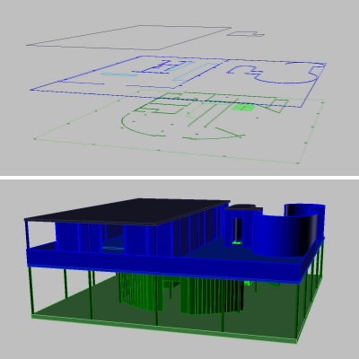
The "CAD Factory" approach refers to a method of drawing production, while at the same time building an explicit history of the decisions and steps of that reflect the way it has been constructed. This approach can be used for 2d and 3D modeling.
It is a method of creating multiple instances of your digital model by copying and dragging your model adjacent to the previous instance.
This workflow is intended to preserve steps while at the same time allows comparison between the new and old instances.
This approach may also serve as a drawing product, illustrating the design process through a series of discrete decisions. From the procession of digital models, diagrams can be distilled as a catalyst to discuss the decisions.
Jigs
The term "jig" refers to a disposable, auxiliary object created for the purposes of dimensionally guiding the creation of an indispensable, product-oriented object.
Jigs are closely related to construction geometry and are often the starting point of any complex 3d model. A jig might be as simple as a measured rectangle within which an object can be created, within the dimensions of that rectangle.
Level of Detail
Depending on the scale you'll be exporting your images or drawings to, your level of detail will have to accommodate it. For example, extremely detailed window mullions won't be able to be seen from an urban context view of a model, but you will be able to see them in a 2d detail drawing at 1/4" scale. It's important to remember that the more geometry that is in a CAD file the larger the file becomes and the more demanding it becomes of your computer's resources.
Utilize layers to create the same object at multiple levels of detail. Begin with the least detailed level (a massing model) and add detail with each successive layer. Using this approach, when you're ready to export or render, you'll enjoy more flexibility and have much better results.